Overview
This is a memo on how to create polylines using the polygon tool in Annotorious v2.
Background
The Annotorious v2 website is available at the following link.
https://annotorious.github.io/getting-started/
As shown below, polygons can be drawn.

However, a tool for drawing polylines in a similar manner did not appear to be provided, including the following plugin.
https://github.com/annotorious/annotorious-v2-selector-pack
Customization
When a polygon like the following is created:
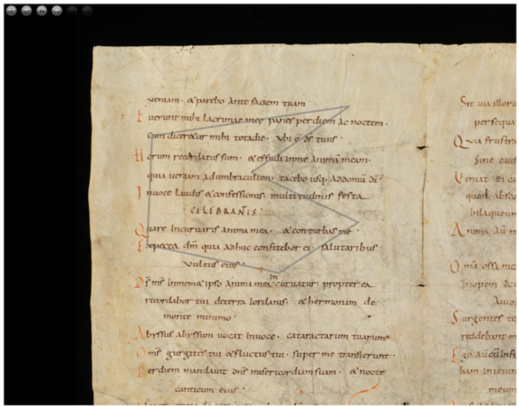
The following JSON file is generated:
{
    "type": "Annotation",
    "body": [
        {
            "type": "TextualBody",
            "value": "polygon",
            "purpose": "commenting"
        }
    ],
    "target": {
        "source": "https://www.e-codices.unifr.ch/loris/gau/gau-Fragment/gau-Fragment_frag001a.jp2/full/full/0/default/jpg",
        "selector": {
            "type": "SvgSelector",
            "value": "<svg><polygon points=\"3383.121337890625,1290.137451171875 945.135498046875,1658.426513671875 885.9696655273438,3003.352294921875 2508.54150390625,3348.424072265625 3485.021484375,2724.35791015625 2170.811767578125,2107.6337890625\" /></svg>"
        }
    },
    "@context": "http://www.w3.org/ns/anno.jsonld",
    "id": "#c469b1a3-8902-4443-8f54-47df8bb87d7e"
}
For the above, I prepared a variable like autoClose, and when it is false, added processing to replace the string “polygon” with “polyline.”
anno.on("createAnnotation", function (selection: any) {
      if(!autoClose.value) {
        selection.target.selector.value = selection.target.selector.value.replace("polygon", "polyline");
      }
      ...
    });
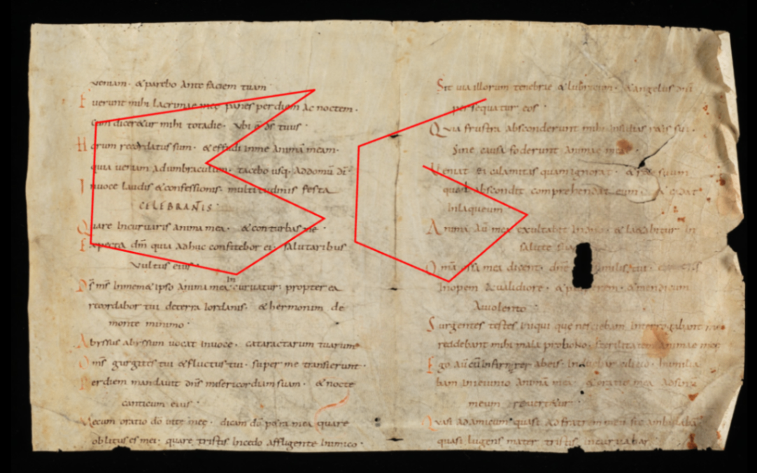
This allows you to switch between polygon and polyline based on the polygon tool, as shown below.
Representation in TEI/XML
As an example of polygon representation in TEI/XML, you can use the path element. In this case, for polygons, the starting point is added after the ending point to represent a closed shape.
<facsimile>
  <surface ulx="0" uly="0" lrx="8176" lry="6132">
    <graphic url="https://www.e-codices.unifr.ch/loris/gau/gau-Fragment/gau-Fragment_frag001a.jp2/full/full/0/default/jpg" />
    <zone xml:id="layer_000" change="#ch_layer_000" n="layer_01" type="layer">
      <zone xml:id="sign_layer_000_0000" change="#ch_sign_layer_000_0000" type="sign">
        <!-- polygon -->
        <path points="1290.137451171875,3383.121337890625 1658.426513671875,945.135498046875 3003.352294921875,885.9696655273438 3348.424072265625,2508.54150390625 2724.35791015625,3485.021484375 2107.6337890625,2170.811767578125 1290.137451171875,3383.121337890625"></path>
      </zone>
      <zone xml:id="sign_layer_000_0001" change="#ch_sign_layer_000_0001" type="sign">
        <!-- polyline -->
        <path points="1393.265625,5290.81005859375 1921.02783203125,3869.745849609375 2982.731689453125,3829.64013671875 3428.122802734375,4874.005859375 2683.244384765625,5741.7509765625 2138.024169921875,4582.19775390625"></path>
      </zone>
    </zone>
  </surface>
</facsimile>
Depending on the application, closed shapes may be drawn even when the start and end points do not match, but we hope this serves as a useful reference for distinguishing between polygon and polyline.
Summary
We hope this serves as a useful reference for expressing polylines using Annotorious v2.
Note that the latest version of Annotorious is v3, and a similar approach should be applicable there as well.